Cisco IOS on VIRL2/CML
Commands for router (or switch)
?displays all the commands availableenableorentakes us into privilleged modeenable ?and tabbing would show other options for the enable command
configure terminalorconf tto change the configuration. (global config mode)host R1to set the hostname toR1interface gigabitEthernet 0/0/0to select the interfaceno shutdownto enable the interface. By default, router interfaces are shutdown.ip address 10.1.1.1 255.255.255.0to configure the ip addressendto exit from config mode, back to the privilleged shell- try to
ping 10.1.1.1(self) from the enable/privilleged mode copy running-config startup-configsaves the config as the startup configwris an older command to write the configsh run(show run) to see the running config of the routershow ip int br(show ip interface brief) for brief overview of all interfacesshow arpshows the arp tableshow usersshows the logged in sessions and some connection info- from a router, simply typing an ip would try to telnet to that ip
show ip routeto see the routing tables- if this shows "Default gateway is not set", maybe ip routing is just not
enabled. go to
conf tand useip routingto enable it
- if this shows "Default gateway is not set", maybe ip routing is just not
enabled. go to
- if youre not getting any console messages, you can specify to show those in
the current session by using
terminal monitorin the enable mode - if you wanna configure 2 interfaces the same way, it can be done using
interface range gig 0/0, gig 1/2. any configuration will apply to both these interfaces. (prolly dont need for now). you could also do something likeint range gig 0/1-2
Routing
- cisco routers usually have ip routing enabled. (because its a router. duh). A
multi-layer switch can route for others but routing is not enabled by default.
this can be turned on using
ip routing - most configurations can be disabled by prepending a
nobefore the command. so for eg, to disable routing, it would beno ip routing - a default gateway can be configured for a switch using
ip default-gateway 10.0.1.1. note that this is different from default route for routing decisions. default gateway is for devices that dont route for others. default route is for a frustrated router that has no other choice :). verify that the gateway was set usingshow ip route - for a device that does ip routing, a default gateway is not used. it used the
default route for routing packets that it doesnt know of. ip routing is
usually done by routers, but an L3 switch can also act as a router by enabling
ip routing. - Routing can be done using
- Directly connected interfaces
- Static routes
- Dynamic routing using protocols like ospf (see ospf)
NAT/PAT
-
To create a pool of ips, use
ip nat pool MY-POOL 1.1.1.1 1.1.1.254 netmask 255.255.255.0. The netmask can also be replaced by theprefix-length /24 -
Now we need an access list to match ips for out NAT rules
-
show access listshows the access list useful to setup rules / for setting up NAT/PAT -
Add rule to access list to specify which addresses to nat by using
access-list 1 permit 172.16.0.0 0.0.255.255on conf t mode. Note that the last field is the wildcard bit and not a mask. Note that a standard access list can only match on source ip address information. For NAT, this is all we really need. Extended ACLs can match on source/destination ip address and ports, and even match on different layer 4 protocols like tcp/udp. -
specify the inside and outside interfces using
int gig 0/0->ip nat outint gig 0/1->ip nat inside
-
specify the nat rule using
ip nat inside source list 1 interface gig 0/0 overload. g0/0 is the outside interface. overload specifies to use PAT to allow a lot of devices. -
verify the translations working with
do show ip nat translations -
1:1 NAT is static
-
N:N (pool to pool) is dynamic
-
N:1 is overload or PAT
NAT lingo
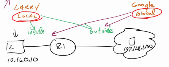
- Inside Local: Inside ip from larry's perspective: his ip
- Outside Local: Outside ip from Larry's perspective: google's ip
- Inside Global: Inside ip from google's perspectie: router's external-facing ip
- Outside global: Outside ip from google's perspective: google's ip
- anytime you see local, its larry's perspective. and anytime you see flobal, its google's perspective
Outside nat (this can get ugly ;p)
- to set the rule, use
ip nat outside source static 192.168.1.100 10.16.6.100 add-route- the format is
ip nat outside source static <outside global> <outside local> add-route - outside local is the ip of google from google's perspective. outside local is ip of outside(google) from larry's perspective (that he believes), which in case of outside NAT will be the ip after the NAT that he will go to to visit google.
- the
add-routeis needed here because both the ips (larry's and natted 10.16.6.100) are on the LAN side. so by default, the router does not have to forward it (same network so why forward). But for NAT to occour, there must be routing. add-route adds a 32 bit static route for this, which will look something like10.16.6.100/32 [1/0] via 192.168.1.100
- the format is
OSPF
- Routers need to agree on the following to form neighbourships:
- Timers: hello messages etc
- Network/subnet
- Authentication
- DR for the segment
- Area type (for CCNA, usually single area - the backbone). other area types like stub areas exist
- DRs not needed for p2p (or point to multipoint) links (serial), They go into full adjacency with everybody.
- DRs only needed
- In a usual network, the routers have an LSA of type 1. the DR will have an LSA of type 2 which will have its own information, its network and also the connected routers
- In case its the only router in the network, it will connect itself to "stub"
area and not generate LSA type 2s. this can be verified by viewing the
database
show ip ospf database. When another router shows up, it will start advertising the LSA typ2 2s and switch from stub to a Transit area, where there are multiple ospf speakers - Note that if there is only one router and that is the DR, it will not generate a tye 2 LSA (because its unnecessary). So type 2 LSAs are used only when there are 2 or more routers present (running ospf) on that network
show ip protocolsshaows what all routing protocols are runningshow ip ospf int brieffor info on ospf interfaces (can be used to check full adjacency)- in
conf tmode,do show ip protocolshows the routing protocols. (lets say we have ospf 1) - go to ospf 1 manage using
router ospf 1 router-id 111.111.111.111to set the ospf router id. this must be unique across neighbours- specify the network using
network 10.0.12.0 0.0.0.255 area 0to set it to the area. this will make the router check all its inerfaces and if any of the ipv4 addresses start with10.0.12, it will make it participate in area 0 of ospf. any directly connected networks to those matching interfaces (whatever mask they may be) will also be included in ospf and be advertised and shared with the ospf network. again, this only looks at the ip of the interface, not its subnet mask - now the ospf neighbours will have to elect and decide on a DR, BDR and go through the ITELF process to reach full adjacency
show ip ospf neighbourwill show the neighbourshipsdefault-information originatewill impose any default static routes to the ospf so every other ospf router will learn the route. This would be needed if a router is not advertising its default route, causing other routers to not have that route information.default-information originate alwayswill always advertise the default route even if it doesnt have a default route.
VLAN
show vlan brief: show available vlans and the associated interfacesshow int trunk: to see details for trunking and associated vlans. note that all swithes in the path of a vlan need to be aware of the vlan, even if they are trunking. otherwise, that packet may be dropped- create a vlan in
conf tmode usingvlan 10. If the vlan doesnt already exists, it will be created when you assign an interface. so this step is not compulsory. but its good to be explicit - from
conf tmode, select the interface you want to assign to the vlan usingint g 0/1 - specify the switchport mode using
switchport mode access. For now, we are creating access ports and not trunking - specify the vlan to use using
switchport access vlan 10
Trunking
- from
conf t, select the interface to be used for truning usingint g 0/1 - specify the 802.1q standard using
switchport trunk encapsulation dot1qto be used for tagging - use
switchport mode trunkto set the switchport mode to trunking, (and not "access" or "dynamic negotiation") and youre done! - verify using
show interfaces trunk
DHCP
-
we first need to specify addresses that are excluded from the dhcp range. this is done using
ip dhcp excluded-address 10.0.0.1 10.0.0.10. The format is first address followed by the last address. So the above command would exclude the addresses 10.0.0.1-10 from being distributed. This is needed before configuring the pool. individual addresses can also be excluded by not specifying a second ip. -
Now, create a dhcp pool using
ip dhcp pool THE-TEN-POOL. This will create a pool named THE-TEN-POOL and enter the dhcp-config mode. If such a pool already exists, it will just go to edit it. -
network 10.0.0.0 255.255.255.0to specify the range of addressed to hand out. You can also specify the prefix length as well here (quite rare for cisco). sonetwork 10.0.0.0 /24also works to the hosts. -
default router 10.0.0.1to specify the default gateway -
dns-server 10.0.0.1to specify the dns server. multiple addresses can also be specifed by daisy chaining. eg:dns-server 10.0.0.1 1.1.1.1 8.8.8.8 -
The lease time can be secified by
lease 1 2 3, the format islease <days> <hours> <minutes> -
see more options that can be configured using
?. Finally, useexitto exit out of the dhcp-config mode -
the leases/bindings can be viewed using
show ip dhcp binding -
to make a router use a dhcp address for itself, use
ip address dhcpbeforeno shut -
to configure a router as a relay, select the interface at which the addresses should be distributed using
int g0/1. now set the relay usingip helper-address 192.168.12.1where 192.168.12.1 is the address of the relay on the other network. 192.168.12.1 should be reachable by this router. but the dhcp server may choose to distribute adresses from a different pool than this address
STP
- Root Switch is selected: Uses oldest (manufactured) switch unless configured otherwise.
- Root port is selected based on the better path, using the following criteria
with decreasing priority:
- Lowest Cost. (gigabit has cost 4, FE has cost 19)
- Lower bridge id. (bridgeid of the from 32582.1111.2222.3333 here 32582 can be configured. the rest is the mac address)
- Lower port number now, the port with the better path is called the root port
- it will turn on 1 designated port per segment. a designated port is a port that is active/alive/forwarding. a segment is any switch link. Now this will also follow the same priority rules as selecting the root port. Note that all ports attackhed to the root switch becomes designated ports.
- Any other ports that are left (neither root nor designated ports) are blocked
ROAS
- The secret is to create sub interfaces on the interface attached to the trunk port and configure it like any other port
- Use
int gig 0/0.10to create the.10sub interface - Now configure trunking and vlans. (to be added)
Switch
On packet tracer, the switch might be powered off by default. add a power module by dragging it into the switch. (physical tab)
Note that switch interfaces, by default come up. rouer interfaces are shutdown by default
It might take a while for the interfaces to go from orange to green. It is waiting for the spanning trees to check for any loops in the network